
RG6 usually wins the first quote because it is familiar, easy to route, and stocked almost everywhere. The field problem shows up later: a 75 ohm path passes continuity, then the receiver margin disappears over a 120 m run, or a larger RG11 cable is forced through a bend radius the enclosure never allowed. The choice is not RG6 versus RG11 in isolation. It is loss budget, routing space, connector termination, and inspection discipline.
This is the selection logic we use before quoting Cable Assembly (hub) work with 75 ohm coax. RG6 and RG11 can both be correct. They fail for different reasons when the drawing only says "coax cable" and leaves impedance, jacket rating, connector type, length tolerance, and test method unstated.
Start with the electrical path, not the cable name
RG6 and RG11 are commonly used as 75 ohm coaxial cable families. That impedance callout has to appear on the drawing because 50 ohm RF parts can look mechanically similar at the connector level. The assembly may use F-type compression connectors, BNC, or another 75 ohm interface, but the cable, connector, mating jack, and test fixture have to agree. A 75 ohm cable terminated into the wrong connector body is not fixed by a continuity pass.
The practical difference starts with conductor size and cable diameter. Common RG6 constructions use an 18 AWG center conductor and an outside diameter near 6.9 mm. Common RG11 constructions use a 14 AWG center conductor and an outside diameter near 10.3 mm. Those are not universal release dimensions; the cable manufacturer's datasheet wins. They are useful quoting numbers because they predict routing force, bend radius, connector ferrule size, package volume, and operator handling risk.
For Coaxial Cable Assemblies, we ask for cable family, exact manufacturer series if locked, impedance, connector interface, finished length, length tolerance, jacket rating, and electrical acceptance limit. If the RFQ says only "RG6, 10 pcs," engineering has to stop. If it says "75 ohm RG6/U, F-type compression both ends, 3,000 mm finished length, +/-10 mm, 100% continuity and shield isolation," the job can move into DFM without guessing.
Where RG6 is usually the better fit
RG6 is the default when the run length is moderate and the assembly has to fit inside real equipment. Its smaller diameter matters. A 6.9 mm cable can route through tighter clips, smaller glands, and denser harness branches than a 10.3 mm RG11 cable. For short equipment jumpers, cabinet interconnects, camera feeds, and many antenna or sensor leads, that mechanical advantage matters more than the extra loss headroom RG11 would provide.
RG6 is also easier to package and easier to terminate repeatedly. The cable is lighter, takes less space on a harness board, and puts less bending load into the connector exit. On a 500 mm jumper, RG11 may create more reliability risk by stressing the connector than it removes through lower attenuation. If the assembly exits a small enclosure, routes through a moving door, or shares a bundle with power and signal leads, RG6 often keeps the build manufacturable.
The mistake is using RG6 as the automatic choice for every 75 ohm path. Once the run moves from cabinet-scale to building-scale, vehicle-scale, or yard-scale, insertion loss becomes the design constraint. We flag RG6 runs above 100 m when the drawing does not include a loss budget, operating frequency, or receiver margin. The cable may still be right, but the decision needs numbers instead of habit.
Where RG11 earns the larger diameter
RG11 is selected when the signal path needs lower attenuation over a longer distance and the product can tolerate the mechanical penalty. The larger 14 AWG center conductor and thicker dielectric reduce loss compared with common RG6 constructions at the same frequency and length. That is why RG11 appears in longer CATV, broadband, surveillance, and site-distribution runs where the cable is routed once and then left alone.
The production tradeoff is real. A 10.3 mm OD cable needs larger connector hardware, more bend allowance, bigger labels, larger packaging, and more attention at strain relief. If the drawing routes RG11 through a 25 mm radius corner, the cable choice and mechanical design disagree. In DFM we often run a conservative 10x OD routing check when the customer has not supplied a cable-specific minimum bend radius. That makes the review radius roughly 69 mm for RG6 and 103 mm for RG11 before the cable datasheet is even opened.
RG11 also changes operator ergonomics. Cutting and stripping larger coax takes more fixture control because braid foldback, foil damage, dielectric nicking, and center-conductor exposure are easier to see but harder to correct after the connector is loaded. The larger cable can make a clean-looking termination that still fails return-loss or pull checks if the ferrule position is wrong by a small amount.
Connector and jacket choices can override the cable choice
RG6 versus RG11 is not the full BOM. The connector interface and jacket rating may decide the assembly before loss does. F-type compression is common for broadband and video-style 75 ohm work. BNC is common where technicians need a bayonet service interface. If the equipment sees washdown, UV exposure, oil mist, or outdoor temperature cycling, the jacket material and sealing method can matter more than the nominal RG family.
Standards language helps prevent substitutions. IPC/WHMA-A-620 workmanship should govern cable and wire-harness operations such as stripping, shield handling, crimping, soldering where used, labeling, and inspection. UL 444 applies when the cable is a communications cable with listing requirements for installation. If the program needs plenum, riser, outdoor, or direct-burial behavior, that requirement belongs in the cable specification. "RG11" alone does not tell a supplier what flame rating, UV resistance, or jacket compound to buy.
The RFQ should also define the finished length reference points. Connector face-to-face, cable cut length, and rear-shell-to-rear-shell are three different dimensions. For short RF Cable Assemblies, a +/-5 mm finished-length tolerance may be reasonable. For long site cables, +/-1% may be more practical. The drawing should say which tolerance applies, because forcing a 50 m RG11 assembly into a jumper-style tolerance adds cost without improving field performance.
How VeinWire handles this in production
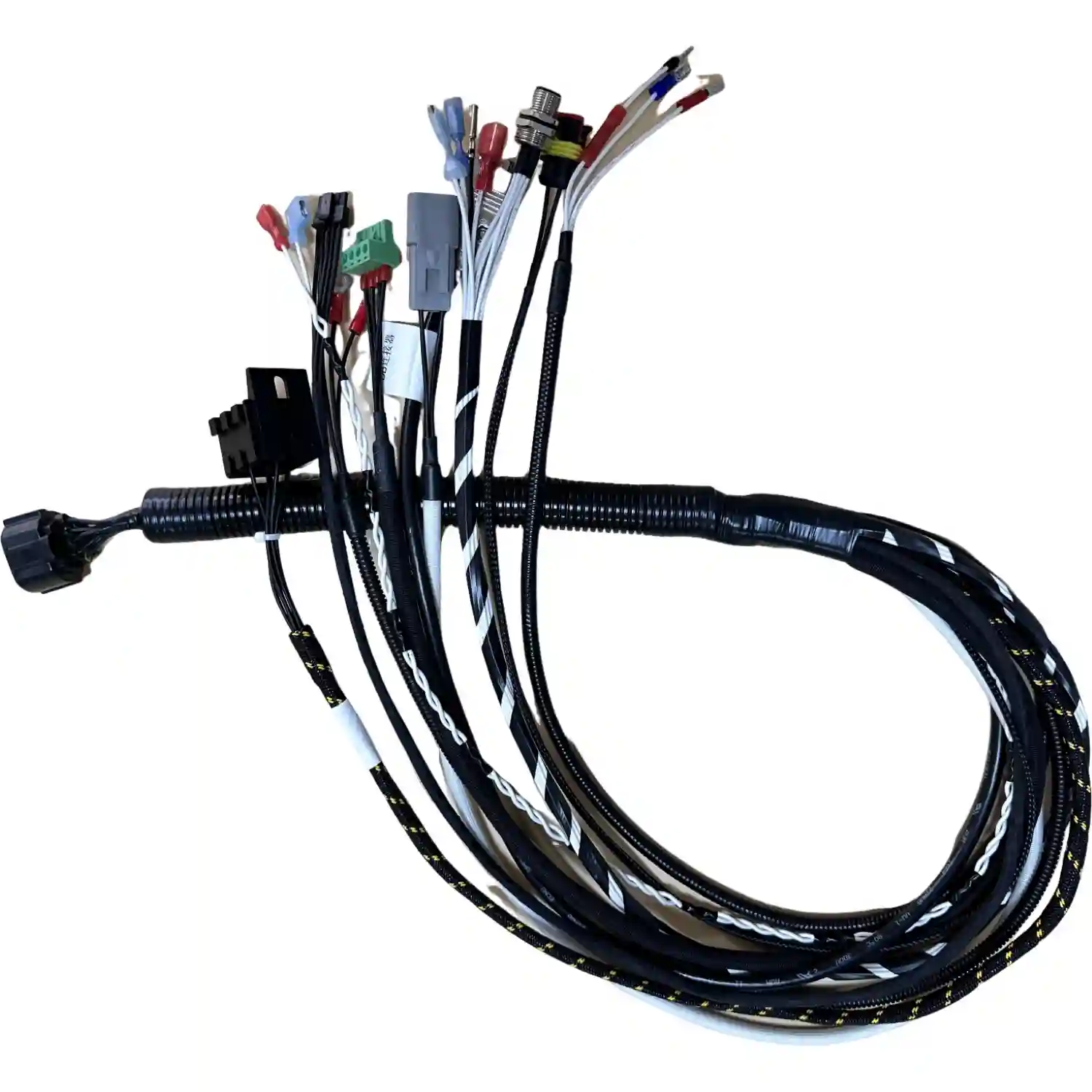
Our first gate is DFM. We check impedance, cable family, connector interface, jacket rating, length tolerance, bend allowance, labeling, and test requirement before release. If the drawing calls out RG6 or RG11 without connector details, we ask for the mating interface instead of assuming. If the cable has to sit inside a larger harness, we review branch routing and clamp points the same way we would for Mining & Heavy-Duty Wire Harness builds, where vibration and service routing can turn a correct cable into a field failure.
At the workstation, operators build to a strip chart tied to the cable and connector datasheets. The inspection points are center-conductor length, dielectric face condition, foil and braid position, ferrule seating, jacket support, label orientation, and connector retention. We use Cirris 1000H fixtures for continuity and shield isolation where the assembly geometry supports it. For RF-sensitive builds, continuity is only the first gate; insertion loss, return loss, or sweep testing has to be specified by the customer because the acceptable limit depends on frequency and system margin.
Sampling depends on risk. Prototype lots often get 100% visual inspection and 100% continuity. Mature production can move some cosmetic checks to AQL sampling after first-article approval, but connector retention and electrical checks stay tied to the drawing. This is the same discipline behind our Testing & Inspection process: the test plan must match the failure mode. A coax assembly that passes only open/short testing has not necessarily proven impedance control or RF performance.
Case in production: An AI and robotics technology company required custom cable assemblies integrating multiple premium connector brands for their advanced automation systems.
Challenge: The client needed a contract manufacturer capable of sourcing and assembling custom cables using a diverse mix of connector brands (JST, TE, MOLEX, ANDERSON, SUMITOMO) while ensuring compliance with rigorous quality standards for high-reliability robotic applications.
What we did: Consolidated multi-brand connector sourcing and custom assembly under ISO 9001:2015 and IATF 16949:2016 certified manufacturing processes, strictly adhering to IPC/WHMA-A-620 production standards to meet the client's high-reliability requirements.
Result: Successfully qualified as the manufacturing partner, securing an initial production order and establishing a baseline for ongoing high-tech robotics manufacturing support.
Concrete numbers: ISO 9001:2015, IATF 16949:2016, IPC/WHMA-A-620, 5 premium connector brands (JST, TE, MOLEX, ANDERSON, SUMITOMO), 1 initial production order
When to choose each cable
Choose RG6 when the run is short to moderate, routing space is limited, the connector exit needs lower mechanical load, and the loss budget still has margin. Choose RG11 when the run is long, the operating frequency and receiver margin justify lower attenuation, and the mechanical design can accept a larger cable, larger connector hardware, and a wider bend radius.
The procurement rule is simple: do not let the cable family carry the whole specification. A complete coax RFQ names the 75 ohm requirement, cable construction or approved manufacturer list, connector interface, finished length reference, tolerance, jacket rating, workmanship standard, and electrical acceptance test. For adjacent wire-size decisions in the same harness, conductor size alone is never the full current-rating answer.
Have a drawing or BOM? Submit it at /contact - engineering walks every drawing within 4 business hours.


